Digital Logic Probe Pen | DTL TTL CMOS Circuit Tester & Analyzer | Logiic
$23.00
$28.78
-20% OFF
Global Shipping
Easy Returns
Secure Payment
Product Description
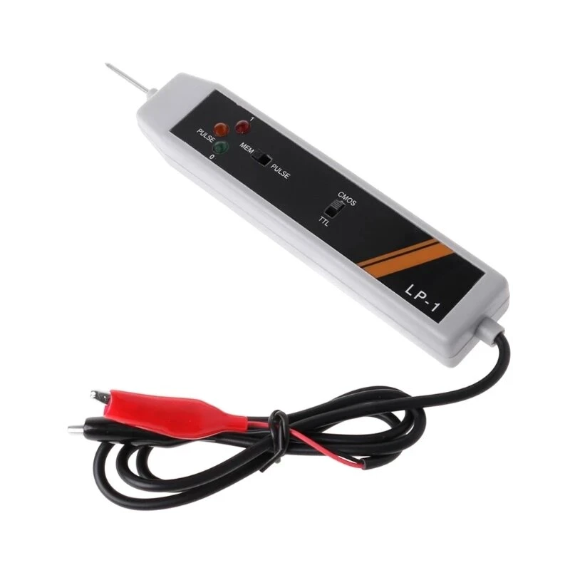
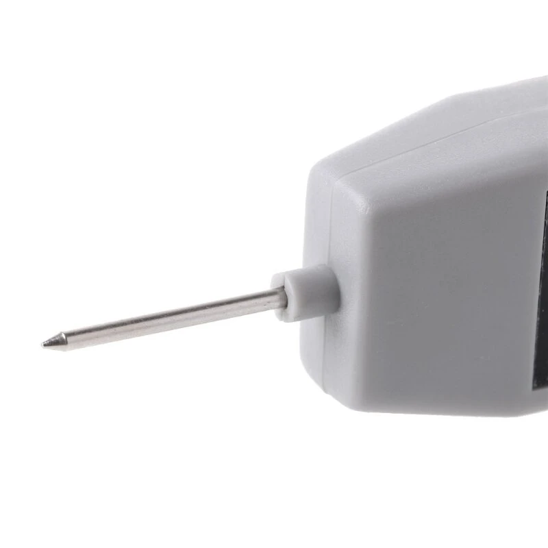
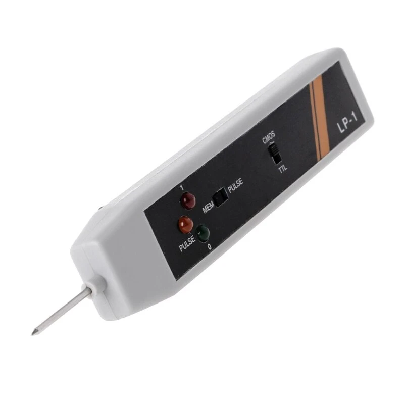
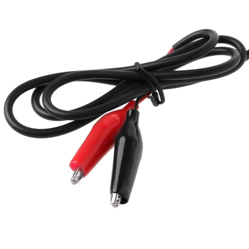
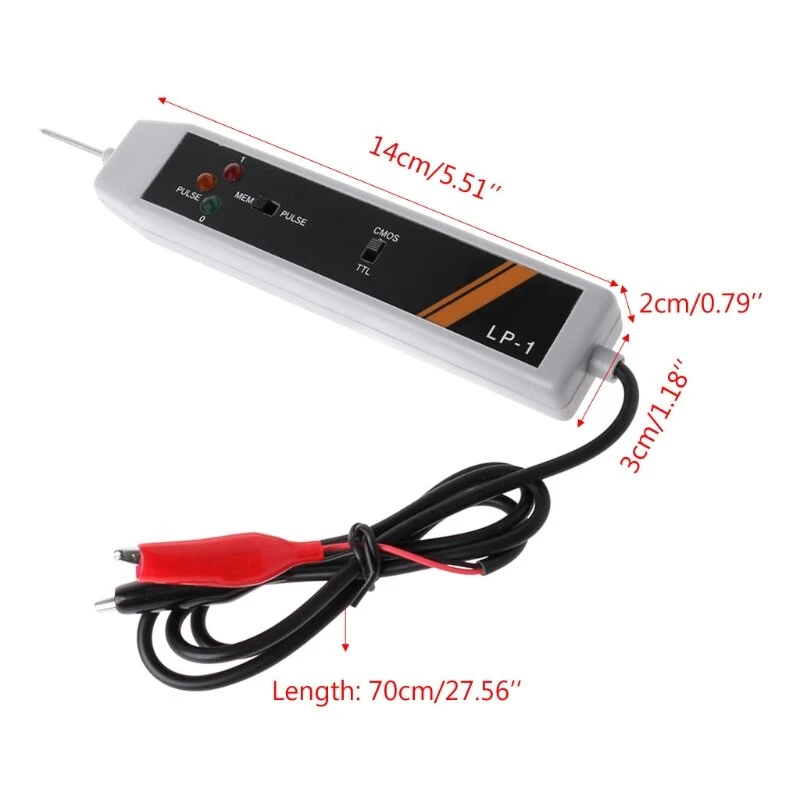
Features: 100% quality and Brand new. Connect RED clip to + terminal and BLACK clip to - terminal of the power source of the circuit under test. the supply voltage should not exceed 18v DC For TTL and DTL, set the upper select switch to the side marked "TTL". for COMS, set the upper select switch to the side marked "CMOS". contact the probe pin to the point to be tested, the LED's will indicate its logiic states: A: ALL LEDs OFF ---- HIGH IMPEDANCE B: RED LED ON ------HIGH STATE [ 1 ] C: GREEN LED ON --- LOW STATE [0 ] D: ORANGE LED ON -- PULSE For detecting and storing pulse or level transition set lower select switch to side marked " PULSE" first. contact the probe pin to the point to be tested. the LED's will indicate its basic state Then set the lower select switch to side marked " MEM", the orange LED will light when any pulse or level transition is detected. teh pulse direction, in comparison with the original basic state, can be determined. After use, reset logiic probe by setting the lower select switch back to the side marked " PULSE" Specification: Color:Black or White(Random Color) Size:15*3*2cm Length:17.5cm Needle length:2.5cm Package Included: 1 x Logiic Pulser Probe Analyzer Circuit Tester Details pictures:Customer Reviews
No reviews yet. Be the first to review this product!